 2025-02-21
1、 Technical Description
The hydrodynamic fully automatic flood control gate is composed of a ground bottom frame, a rotatable water blocking door fan, and rubber soft plates for water stop at the ends of the two side walls. When encountering flood backflow, water flows into the lower part of the water blocking valve fan through the inlet at the front end of the ground frame. When the water level is higher than the height of the whole machine and reaches the trigger value, buoyancy pushes the front end of the water blocking valve fan to flip upward, thereby achieving automatic water blocking; When there is no water, the water blocking door leaf lies on the ground frame, allowing vehicles and pedestrians to pass without obstacles. It can also have smart sensing and remote networking functions, and can upload water conditions and work status in real time. The gate height includes three conventional heights: 600mm, 900mm, and 1200mm, while other heights can be customized; The standard module width of the gate is 600mm, and the maximum width of a single gate can reach 10m.
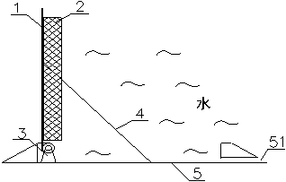
The fully automatic flood control gate for underground and low-lying buildings is based on pure physical principles. When water flows back, the gate will automatically float and lower with the water level. The specific implementation is as follows: the working status of the fully automatic flood control gate for underground and low-lying buildings is shown in Figure 1-1, Figure 1-2, and Figure 1-3, including panel 1, hinge seat 3, and base 5. The hinge seat 3 is set at one end of the base 5, and one end of the panel 1 is hinged to the hinge seat 3. The other end can rotate in a circular arc along the hinge seat 3. One end of the base 5 is equipped with an inlet and outlet hole 51, and the floating plate 2 is set on the side of panel 1 near the base 5; When water enters the base 5 from the space above the inlet and outlet holes 51 or the base 5, the floating plate 2 can drive the panel 1 to rotate upward along the hinge seat 3 under the buoyancy of the water. Float plate 2 is preferably hollow box, plastic or foam, and panel 1 is preferably made of high-strength aluminum alloy. In addition, reinforcement ribs can be installed on panel 1 to increase its load-bearing capacity.


2、 Main performance indicators
1. Control mode: fully automatic, also capable of manual operation;
2. Gate height: 600mm, 900mm, 1200mm three conventional heights, other heights can be customized;
3. Gate width: The standard module width is 600mm, and the maximum width of a single gate can reach 10m;
4. Scope of adaptation: Entrance and exit of underground buildings (including civil defense engineering, underground garages, subway stations, underground shopping malls, underground warehouses, pedestrian walkways, and underground pipe galleries) and low-lying buildings or areas on the ground, both flat and sloping;
5. Installation method: Surface and embedded installation can be selected for a height of 600mm, while embedded installation is only available for heights of 900mm and 1200mm;
6. Service life: 12 years.
3、 Scope of application and application conditions
Suitable for water blocking and backflow prevention projects at entrances and exits of underground spaces such as subways and underground parking lots.
Application conditions: Installation ground flatness ≤ 2mm/M; Wall installation height (600mm board) L ≥ 700mm, (400mm board) L ≥ 450mm.
4、 Key points of construction and installation
1. Requirements for surface mounted installation surfaces

(1) Surface installation location: ① About 5cm above the ground to prevent damage to the vehicle or flood control gate when the vehicle is fully loaded. The minimum ground clearance when the sedan is fully loaded is: B70=95mm, Accord=100mm, Fit=105mm, etc The location should be on the horizontal section at the top of the slope, inside the outermost intercepting ditch, or installed on top of the intercepting ditch. Reason: Small water can be drained away through intercepting ditches; Can prevent backflow and backflow from the interception ditch when the municipal pipeline is full of water The higher the installation position, the higher the water blocking level.
(2) Levelness of installation surface: The horizontal height difference between the ends of the walls on both sides of the installation surface is ≤ 30mm (measured using a laser level).
(3) Flatness of installation surface: ① Referring to the "Code for Acceptance of Construction Quality of Building Ground Engineering" GB50209, the deviation of surface flatness should be ≤ 2mm (measured with a 2m ruler and wedge-shaped feeler gauge), otherwise the ground should be leveled first, otherwise it will cause water leakage from the bottom frame after installation. ② Especially for floors that have undergone anti slip treatment, they should be leveled first.
(4) Installation surface strength: ① Installation surface with a thickness of Y ≥ 200mm and a horizontal extension of X ≥ 300mm or its equivalent strength, not less than C20 concrete. ② The installation surface shall not have cracks, hollows, or detachment. The concrete shall be inspected and qualified according to the "Code for Acceptance of Construction Quality of Concrete Structures" GB50204. Otherwise, the concrete installation platform shall be remade according to the requirements If it is concrete, it should pass the curing period.
(5) Side wall: ① The height of the side wall is greater than the height of the flood control gate fan, otherwise it should be raised. ② The side wall must be a solid brick, concrete or its equivalent strength installation surface; When installing side walls with metal or non-metal structures, corresponding reinforcement measures should be taken.
2. Requirements for Embedded Installation Surface
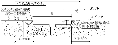
(1) Embedded installation slot position: ① It should be set behind the outermost intercepting ditch. Reason: Small water can be drained away through intercepting ditches; It is necessary to prevent the backflow of water from the interception ditch when the municipal pipeline is full during floods The higher the installation position, the higher the water blocking level.
(2) Installation of residual water discharge capacity in the groove: ① A 50 * 150 collection tank is reserved at the bottom of the installation groove, and a Φ 100 drainage pipe is reserved at the bottom of the collection tank. ② Emission test: After pouring in a certain amount of water, the water can be smoothly discharged from the drainage pipe.
(3) Levelness of installation surface: The horizontal height difference between the ends of the walls on both sides of the installation surface is ≤ 30mm (measured using a laser level).
(4) Flatness of installation surface: ① Referring to the "Code for Acceptance of Construction Quality of Building Ground Engineering" GB50209, the deviation of surface flatness should be ≤ 2mm (measured with a 2m ruler and wedge-shaped feeler gauge). Otherwise, the ground should be leveled first, otherwise it may cause water leakage from the bottom frame after installation.
(5) Installation surface strength: ① Installation surface with a thickness of not less than C20 concrete, a horizontal extension of X ≥ 300mm around the perimeter, or its equivalent strength. (Y value see attached figure 2) ② There should be no cracks, hollows, or detachment on the installation surface. The concrete should be inspected and qualified according to the "Code for Acceptance of Construction Quality of Concrete Structures" GB50204. Otherwise, the concrete installation platform needs to be remade according to the requirements. ③ If it is concrete, it should pass the curing period.
(6) Side wall: ① The height of the side wall is greater than the height of the flood control gate fan, otherwise it should be raised. ② The side wall must be a solid brick, concrete or its equivalent strength installation surface; When installing side walls with metal or non-metal structures, corresponding reinforcement measures should be taken.
Exquisite principle, safe and reliable
When there is no water, flood gates act like speed limits for vehicles, allowing pedestrians and vehicles to pass through without obstacles. When encountering water backflow, the water flows from the front inlet of the ground frame into the lower part of the water blocking valve fan. The buoyancy pushes the front end of the water blocking valve fan to flip upwards, and the flood control gate automatically rises, thus achieving automatic water blocking at all times without the need for electric drive or personnel supervision, which is very safe and reliable.
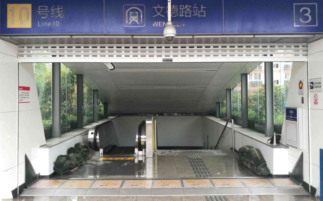
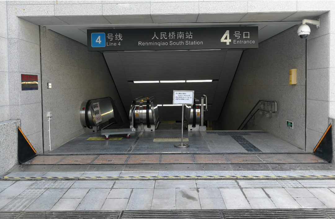
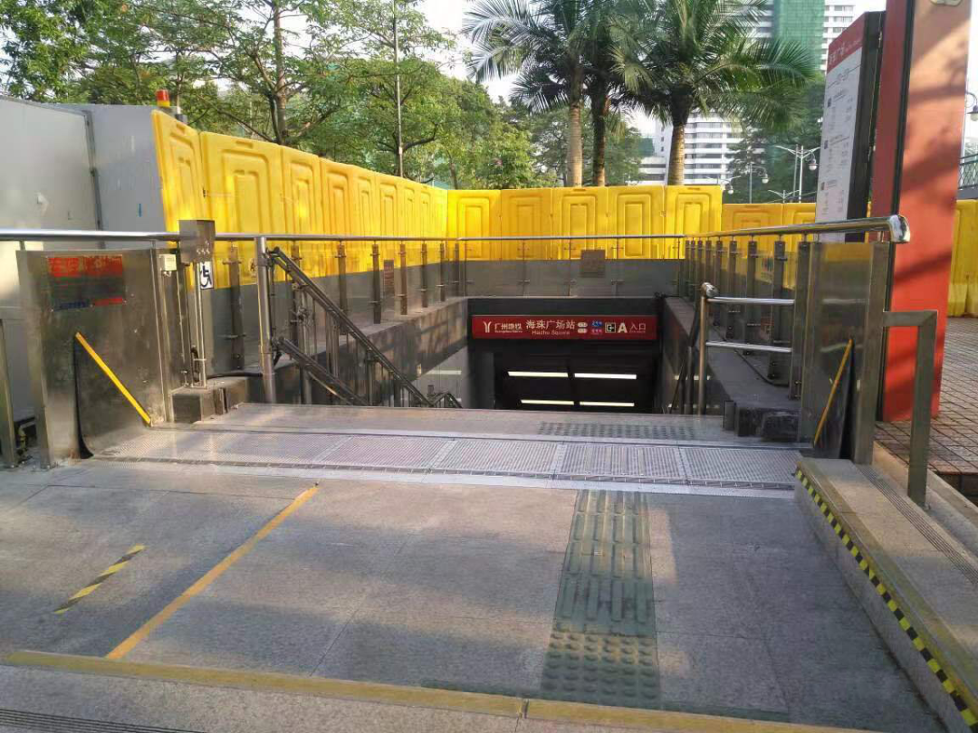
The hydrodynamic automatic flood control gate is a nationally patented technology widely used as an automatic flood control tool for underground buildings that does not require electricity - the hydrodynamic fully automatic flood control gate